Populer Post
Common Timing Advance (TA) in 5G NTN
The Problem: The “Elevator Pitch” Delay
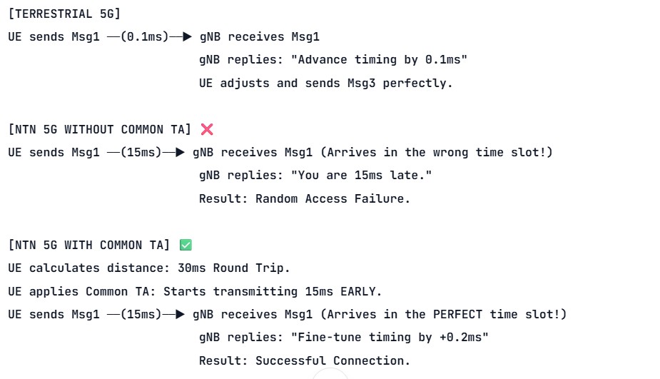
In standard terrestrial 5G, Timing Advance (TA) is a microsecond-level adjustment. The phone sends a random access preamble (Msg1). The cell tower measures how late the signal arrived, calculates the distance, and sends a TA command back to the phone saying, “Transmit 2 microseconds earlier next time.” This happens in a fraction of a millisecond.
In NTN, the distance to the satellite is massive. A signal might take 10 to 15 milliseconds just to travel one way. If the UE waited for the satellite to measure its initial timing and send a correction, the Random Access procedure would take far too long, and the initial signal would likely arrive in the wrong time slot, causing an immediate collision or rejection.
The Solution: Common Timing Advance (Common TA)
To solve this, 3GPP introduced Common TA. Instead of the network guessing the UE’s delay, the UE calculates the baseline delay itself before it even speaks.
Using its GNSS location and the satellite’s reference point (provided in SIB19), the UE calculates the baseline Round-Trip Time (RTT) to the center of the satellite beam. It then applies this “Common TA” to its very first transmission (Msg1 / PRACH).
The UE essentially says, “I know I am far away, so I am going to start transmitting early so my signal arrives at the satellite at the exact right moment.”
Real-World Analogy: Rough Focus vs. Fine Focus
Imagine using a telescope.
- Common TA is like you turning the large focus knob to get the image “roughly” clear based on your own knowledge of how far away the object is.
- Network TA Command is the observatory expert making a tiny, precise “fine focus” adjustment afterward to make the image perfectly sharp.
Without the rough focus (Common TA), the expert would be looking at a completely blurred image and wouldn’t even know where to start adjusting.
June 13, 2026
K-offset: The “Time-Travel” Fix for 5G NTN
If you’ve ever wondered how a 5G phone can talk to a satellite 500 km above Earth, the answer is all about timing.
In normal (terrestrial) 5G networks:
- Signals travel short distances
- So timing is predictable and fast
But in satellite networks (NTN):
- Signals have to travel very long distances
- This causes big delays (called propagation delay)
👉 This delay can confuse the network and break communication timing.
The Fix: K-offset
K-offset is a smart solution introduced in 3GPP Release 17.
It works like this:
- The network intentionally adds extra time (a buffer)
- This gives signals enough time to travel to and from the satellite
- So everything stays properly synchronized.
🤔 The Problem: The “Canyon Echo” Effect
In normal terrestrial 5G, the distance between your phone and the cell tower is small. The network uses fixed timing rules, known as K-values, to schedule things:
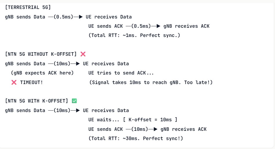
- K1: The time between the phone receiving data (PDSCH) and sending an Acknowledgment (HARQ-ACK). Usually just a few slots (~0.5 milliseconds).
- K2: The time between the network granting permission to speak (UL Grant) and the phone actually transmitting (PUSCH).
The NTN Disaster Scenario:
Imagine a LEO (Low Earth Orbit) satellite with a Round-Trip Time (RTT) of 20 milliseconds. If the gNB (base station) uses the standard terrestrial K1 value of 0.5ms, it will expect the phone’s acknowledgment 20 milliseconds before the phone even received the original message!
The network would constantly time out, assume the connection failed, and drop the call.
💡 The Solution: What is K-offset?
K-offset is essentially a “buffer time” or a “delay offset” broadcast by the satellite to the UE (User Equipment).
Instead of rewriting the entire 5G scheduling rulebook for space, 3GPP simply added K-offset to the existing K1 and K2 values. It tells the UE: “Take the standard timing rule, and add this extra delay to account for the trip to space and back.”
The Simple Formula:
Actual UL Transmission Time = DL Reception Time + Standard K-value (K1/K2) + K-offset
By adding K-offset, the UE intentionally delays its response. This ensures that when the UE finally transmits, the signal arrives at the satellite exactly when the gNB is listening for it.
How is K-offset Configured?
- Broadcast: The satellite includes the
k_Offsetparameter inside SIB19 (System Information Block 19) or provides it via dedicated RRC signaling during connection setup. - Dynamic Adjustment: As a LEO satellite moves across the sky, the distance to the UE changes. The propagation delay changes. Therefore, the network can update the K-offset value dynamically to keep the timing perfectly aligned.
- MAC Layer Patience: K-offset works hand-in-hand with another NTN parameter called K_MAC (which we covered in our SIB19 deep dive). While K-offset delays the start of the UE’s transmission, K_MAC tells the UE’s MAC layer to be “patient” and wait longer for the gNB’s response.
June 13, 2026
Leave a Reply
📡 SIB19: The Brain of 5G NTN Connectivity.
In terrestrial 5G, the distance between a UE (smartphone) and the cell tower is negligible (a few kilometers). Signal delay is ~1ms, and Doppler shift is virtually zero.
In Non-Terrestrial Networks (NTN), the “tower” is a satellite hundreds or thousands of kilometers away. This introduces two massive problems: huge propagation delays (up to 30ms for LEO, 500ms+ for GEO) and extreme Doppler shifts due to satellite movement.
Enter SIB19 (System Information Block Type 19). Introduced in 3GPP Release 17, SIB19 is the specialized broadcast message that gives the UE all the mathematical and timing data it needs to “aim” its signal correctly at a moving satellite. Without SIB19, NTN random access would fail 100% of the time.
SIB19 Information Elements (IEs).
SIB19 contains the NTN-Config IE. Here is a plain-English breakdown of every critical parameter inside it:
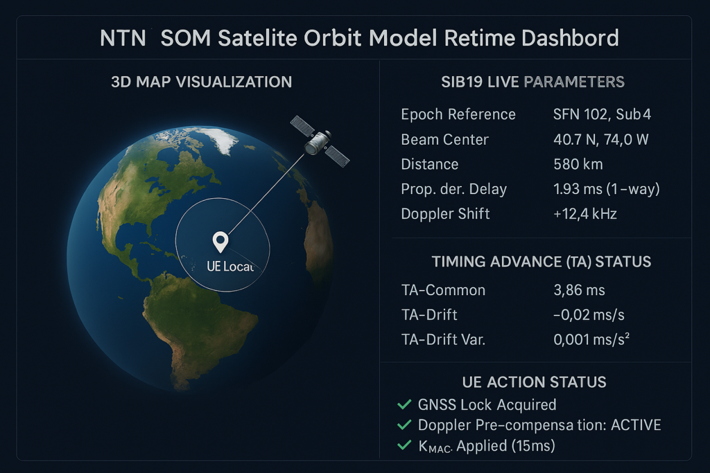
1. epoch (The Reference Time)
- What it is: A specific System Frame Number (SFN) and subframe that acts as “Time Zero.”
- Why it matters: All orbital calculations and timing drifts are relative to this exact moment. It’s like setting a synchronized stopwatch for both the satellite and the UE.
2. orbitModel (The Satellite’s GPS)
- What it is: The mathematical model defining the satellite’s path. It comes in two flavors:
keplerianParameters: A compact set of 6-7 numbers (semi-major axis, eccentricity, inclination, etc.) that the UE’s processor uses to calculate the satellite’s 3D position. Highly efficient for LEO/MEO.ephemerisModel: Used for complex orbits (like GEO with station-keeping wobbles) where simple math isn’t enough.
- Why it matters: Instead of broadcasting massive, continuous GPS-like data, the network sends a formula. The UE calculates the satellite’s location itself, saving precious broadcast bandwidth.
3. ephemerisInfo (The Backup Data)
- What it is: If the orbit is too complex for
keplerianParameters, this IE provides the actual ephemeris data. ephemerisReference: If the data is too large for a broadcast message, this provides a URL (e.g., via HTTP/HTTPS) where the UE can download the precise satellite position file.
4. commonBeamInfo (The Spotlight)
- What it is: Contains the
beamIdand thereferencePoint(latitude/longitude) of the center of the satellite’s beam footprint on Earth. - Why it matters: Helps the UE confirm it is actually inside the intended coverage area before attempting to connect.
5. serviceLinkInfo (The Radio Rules)
- What it is: Defines the
dl-CarrierFreqandul-CarrierFreq. Crucially, it includesdopplerPreCompensation(a boolean: true/false). - Why it matters: If
true, the network (satellite/gNB) is already adjusting the downlink frequency to cancel out Doppler. Iffalse, the UE must calculate and pre-compensate its own uplink frequency before transmitting.
6. ta-Info (The Timing Advance Package)
Because the distance is huge, the UE must transmit early so the signal arrives at the satellite in the correct time slot. This IE provides a 3-part prediction:
ta-Common: The baseline round-trip delay to the satellite’s reference point.ta-CommonDrift: The rate at which this delay is changing (velocity). Essential for LEO satellites moving at 7.5 km/s.ta-CommonDriftVariant: The acceleration of that delay change (the second derivative). Ensures pinpoint accuracy as the satellite passes overhead.
7. k_Mac (The HARQ Patience Parameter)
- What it is: An integer value (in milliseconds or subframes).
- Why it matters: In normal 5G, the UE expects an ACK/NACK for its data in ~3-4ms. In NTN, the signal might take 15ms just to reach the satellite.
k_Mactells the UE’s MAC layer: “Do not assume the transmission failed; wait this long for the response.”
8. ntn-PagingCycle (The Battery Saver)
- What it is: Extended paging cycles (e.g.,
rf640,rf1280,rf2560). - Why it matters: Because the satellite beam sweeps across the Earth, a UE might only be in coverage for a short window. Extended cycles prevent the UE from waking up unnecessarily and draining its battery while waiting for a page that won’t come until the beam returns.
9. earthCoverageInfo (The Geo-Fence)
- What it is: A polygon of latitude/longitude coordinates defining the exact valid footprint of the cell.
- Why it matters: Prevents UEs outside the beam (e.g., in an adjacent country or ocean) from wasting power trying to decode signals or initiate random access.
NTN SIB19 Signaling Flow (Step-by-Step)
Here is the exact sequence of events from the moment a UE powers on in a remote area to successfully connecting via satellite.
-
System Broadcast (gNB ➔ UE)
The satellite broadcasts the MIB, followed by SIB1. SIB1 contains the scheduling information indicating that SIB19 is present in this cell. -
SIB19 Acquisition (UE ➔ Internal)
The UE reads SIB19 and extracts theNTN-Config(Epoch, Orbit Model, TA-Info, K_MAC, etc.). -
GNSS Self-Location (UE ➔ Internal)
The UE activates its GNSS receiver (GPS/Galileo) to determine its own precise latitude, longitude, and altitude. (Note: NTN UEs must be GNSS-capable). -
The NTN Math Engine (UE ➔ Internal)
The UE combines its own GNSS location with the SIB19orbitModelandepoch. It calculates:- Exact 3D distance to the satellite.
- Current propagation delay.
- Relative velocity (to determine Doppler shift).
-
Pre-Compensation (UE ➔ Internal)
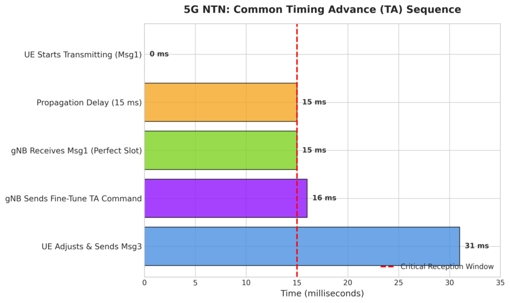
Before transmitting, the UE adjusts its local oscillator (to counter Doppler) and advances its transmission clock usingta-Common+ta-CommonDrift. -
Random Access Preamble (Msg1) (UE ➔ gNB)
The UE sends the PRACH preamble. Because of Step 5, the signal arrives at the satellite perfectly aligned with the gNB’s expected reception window, despite the hundreds of kilometers of travel. -
Random Access Response (Msg2) (gNB ➔ UE)
The gNB receives Msg1. It measures any residual timing error (because the UE’s calculation might be off by a few microseconds). The gNB sends Msg2 (RAR) containing a fine-tuned MAC CE Timing Advance Command to perfect the alignment. -
Normal 5G Operation (UE ⇄ gNB)
The UE applies the fine-tuned TA, respects thek_Macdelay for HARQ feedback, and proceeds with Msg3 (RRC Setup Request) and normal data transmission.
June 13, 2026
Leave a Reply
NTN in 5G: (3GPP Release‑17 Explained)
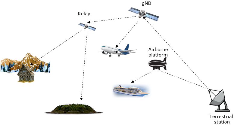
Non‑Terrestrial Networks (NTN) are one of the biggest breakthroughs introduced in 3GPP Release‑17, making 5G capable of connecting users beyond Earth-based towers. Unlike traditional networks that depend on land-based cell sites, NTNs bring connectivity from space and high-altitude platforms, enabling coverage in oceans, mountains, deserts, rural areas, and disaster zones.
3GPP officially defines NTN as communication networks that rely on LEO, MEO, GEO satellites, HAPS platforms, and UAV-based relays to deliver 5G service from above the Earth’s surface.
Why NTN Matters in Modern 5G?
Traditional terrestrial networks cannot reach everywhere. Factors like geography, low population density, and infrastructure cost create coverage gaps. NTNs bridge these gaps using satellites and high-altitude systems, improving:
- Global broadband access
- Emergency & disaster communication
- Maritime & aviation services
- IoT expansion
- Positioning & timing support
3GPP studies highlight that maintaining uplink synchronization, updating satellite ephemeris, and adapting SI (System Information) delivery — especially SIB19 — are essential to maintain stable NTN connectivity.
Types of NTN Platforms
NTN platforms listed by 3GPP include:
1. Low Earth Orbit (LEO) satellites
- 500–2000 km altitude
- Lower latency
- Requires large constellations
2. Medium Earth Orbit (MEO) satellites
- 8000–20,000 km
- Balanced latency and coverage
3. Geostationary Orbit (GEO) satellites
- 35,786 km
- Huge coverage, but higher latency
4. High-Altitude Platforms (HAPS)
Such as balloons or solar-powered aircraft hovering around 20 km altitude.
5. UAV-based Aerial Relays
Used in emergency coverage.
NTN research shows rapid advancements in SIB19 optimization, including compressed ephemeris, AI-assisted beam prediction, and on-board GNSS receivers to reduce error and enhance UE tracking.
SIB19 – The Heart of NTN System Information
SIB19 is a unique NTN-specific System Information Block introduced in 5G Release‑17. It includes:
- Satellite orbit parameters
- Timing correction data
- GNSS assistance
- Beam IDs / satellite identifiers
- UL‑Sync validity timers
3GPP research confirms SIB19 is essential to maintain uplink synchronization in NTN because satellite movement constantly alters delay and Doppler shifts. As a result, UE must periodically reacquire SIB19 based on defined SI periodicity and network algorithms.
How NTN SI (System Information) Works ?
SIB19 is transmitted using SI‑RNTI, same as legacy SIBs(SIB1, SIB2,SIB3, SIB4…). All NTN UEs decode SIB19 using downlink PDSCH just like normal SIBs. However, NTN SI scheduling faces challenges:
- Satellite movement → dynamic SI timing
- Large RTT (Round Trip Time) → scheduling offsets
- SI-window alignment with other SIBs (SIB2–SIB5)
3GPP ensures SIB19 avoids SI-window overlap by defining specific window position rules and scheduling behavior.
Key Challenges in NTN
-
Propagation Delay
Satellite links create much higher RTT. -
Doppler Shift
LEO satellites move at ~7.5 km/s → high frequency shifts. -
Beam Movement
Rapidly changing beam footprints require tracking. -
Power Constraints
Handsets must decode weak signals from hundreds of kilometers away. -
System Information Complexity
SIB19 must carry more dynamic information than terrestrial SIBs.
Benefits of NTN in 5G
- Global coverage
- Reliable communication in remote locations
- Better emergency handling
- Stronger IoT ecosystem
- Aviation & maritime connectivity
March 11, 2026
Leave a Reply
NR NTN Bands
3GPP introduced specific bands for Non-Terrestrial Networks (NTN) to support 5G NR over satellites. These bands are optimized for Mobile Satellite Services (MSS) and Feeder Links.
1. n255 – S-band
- Frequency Range:
- Uplink (UE → Satellite): 1980 MHz – 2010 MHz
- Downlink (Satellite → UE): 2170 MHz – 2200 MHz
- Duplex Mode: FDD
- Use Case:
- Direct UE-to-satellite connectivity for mobile broadband.
- Common for LEO and GEO satellites.
- Advantages:
- Good propagation characteristics.
- Moderate antenna size for UE.
2. n256 – L-band
- Frequency Range:
- Downlink (Satellite → UE): 1525 MHz – 1559 MHz
- Uplink (UE → Satellite): 1626.5 MHz – 1660.5 MHz
- Duplex Mode: FDD
- Use Case:
- MSS services (voice, messaging, IoT).
- Ideal for NTN because of low attenuation and better penetration.
- Advantages:
- Excellent coverage and penetration.
- Smaller bandwidth compared to S-band.
Feeder Link Bands
For connecting satellite ↔ ground gateway, higher frequency bands are used:
- Ka-band: ~27.5–31 GHz (uplink), 17.7–21.2 GHz (downlink)
- Ku-band: ~14 GHz uplink, ~11 GHz downlink
Key Points
- Both n255 and n256 are FDD bands.
- Designed for direct UE-to-satellite links in NTN.
- Support mobility, IoT, and broadband use cases.
December 25, 2025
Leave a Reply
What Are LEO, MEO, GEO, and HEO in 5G Non-Terrestrial Networks (NTN)?
Imagine hiking through a remote mountain trail with no cell signal in sight. You pull out your phone, and suddenly, you’re streaming a video or making a call via satellites overhead. That’s the promise of 5G Non-Terrestrial Networks, or NTN. These systems blend space tech with ground-based 5G to reach places where towers can’t go. From oceans to deserts, NTN fills the gaps. At the heart of this tech are four orbit types: LEO, MEO, GEO, and HEO. They each play a part in making global coverage real.

Understanding Satellite Orbits: The Foundation of NTN Architecture
Satellites zip around Earth in different paths. These paths, or orbits, decide how well they connect with your device. Altitude matters most—it affects speed of signals and the area each satellite covers. In 5G NTN, we pick orbits based on what the job needs. Low ones hug the planet for quick chats. High ones watch over big zones but take longer to reply.
LEO satellites circle close to home. MEO ones sit in the middle range. GEO stays fixed way up there. HEO swings in wild loops for tough spots. Each fits into 5G like pieces of a puzzle. They help build a network that works everywhere.
Low Earth Orbit (LEO): The Latency Game Changer
LEO means Low Earth Orbit, from about 300 to 2,000 kilometers up. These satellites move fast, orbiting Earth in under two hours. For 5G NTN, LEO shines because signals travel short distances. That cuts delay to just 20 to 50 milliseconds—key for video calls or self-driving cars.
Think of LEO like a swarm of bees buzzing near a flower. Companies like SpaceX with Starlink launch thousands of them. This dense setup boosts data speeds up to 100 Mbps per user. But it comes with tricks. Satellites zip by so quick that your phone switches beams often. Ground stations must track them nonstop. Still, LEO leads the charge for mobile 5G in the sky.
Handovers happen every few minutes in LEO systems. That’s when your connection jumps to another satellite. It demands smart software to keep things smooth. Without it, you’d drop calls mid-sentence. Denser gateways on Earth help route data fast. Overall, LEO makes 5G feel instant, even on the move.
Medium Earth Orbit (MEO): Balancing Reach and Latency
MEO stands for Medium Earth Orbit, roughly 2,000 to 35,786 kilometers high. These satellites strike a middle ground. They cover more ground than LEO but lag less than GEO—around 100 to 150 milliseconds. In 5G NTN, MEO suits tasks like internet for ships or planes where some delay is okay.
Picture MEO as a steady handoff between close and far. Constellations like SES’s O3b use about a dozen satellites for worldwide reach. Fewer birds in the sky means lower costs to launch. Each one beams data over huge areas, say 1,000 kilometers wide. That eases the load on ground teams.
You need far fewer MEO satellites for full coverage—maybe 20 versus 10,000 for LEO. This setup saves money on rockets and upkeep. Yet, latency isn’t as zippy as LEO. For 5G, it works well for streaming or emails, not ultra-fast games. MEO blends cost and performance just right.
Geostationary Earth Orbit (GEO): The Legacy Powerhouse
GEO is Geostationary Earth Orbit at exactly 35,786 kilometers. Here, satellites match Earth’s spin, so they hover over one spot. A single GEO bird covers a third of the planet—like the whole U.S. from coast to coast. In old-school telecom, this ruled TV broadcasts and calls.
For 5G NTN, GEO brings stability. No handovers needed since it stays put. But signals take 500 milliseconds round-trip—too slow for quick 5G chats. It fits best as a backup link. Think routing data from remote towers to the internet backbone.
Today, GEO handles backhaul in wild spots like islands or mines. Three satellites ring the equator for basic global watch. Latency hurts interactive apps, sure. Yet for voice or video where timing flexes, it delivers. GEO’s wide footprint makes it a reliable anchor in NTN mixes.
Highly Elliptical Orbit (HEO): Serving the Extremes
HEO refers to Highly Elliptical Orbit, with paths that stretch from near-Earth to far out. These loops linger over poles, like the Arctic or Antarctic, for hours at a time. In 5G NTN, HEO targets high-latitude zones where round orbits fall short. It provides steady signals to frozen outposts.
Envision HEO as a pendulum swinging wide. Systems like Russia’s Molniya design focus on northern reaches. Satellites dwell over key areas, dodging the gaps in LEO or GEO. This setup aids research stations or border patrols. Coverage lasts longer per pass than speedy LEO.
HEO excels in places like Greenland or Siberia. Traditional satellites skim by too fast there. With HEO, you get hours of solid link for data uploads. It’s niche but vital for full 5G reach. Pair it with others, and no spot stays dark.
The Role of Orbital Classification in 5G NTN Performance
Orbits shape how 5G NTN runs. Low ones push speed; high ones stretch coverage. This mix affects everything from signal strength to data flow. Engineers tweak antennas and codes to match each type. Why does it matter? Your phone’s 5G experience changes based on what’s overhead.
We balance trade-offs to fit real needs. LEO zips data but needs crowds of satellites. GEO blankets wide but waits on replies. Understanding this helps build tougher networks.
Latency and Throughput Trade-offs
Latency is the wait time for signals to bounce back. LEO clocks in at 20-50 ms, MEO at 100-150 ms, GEO over 500 ms, and HEO varies by spot—often 200-400 ms near apogee. Throughput follows suit: LEO hits gigabit bursts, while GEO tops at 100 Mbps steady.
Compare it to mail delivery. LEO is like a bike messenger—quick but limited range. GEO’s a truck hauling loads across states, slower but vast. In 5G, link budgets factor distance; higher orbits weaken signals, so bigger dishes help. 5G New Radio tweaks beams to fight this.
Protocols adapt for delays. Doppler shifts in fast LEO twist frequencies, so clocks sync tight. Beam management tracks moving sats. This keeps throughput high—up to 95% efficiency in tests. Pick the orbit, and you tune the network right.
- LEO: Best for low-latency apps like gaming (under 50 ms).
- MEO: Solid for video (100-150 ms, 500 Mbps).
- GEO: Good for broadcasts (500+ ms, wide area).
- HEO: Ideal for polar data (variable, focused coverage).
Satellite-to-Device (S2D) vs. Gateway Links
NTN links split into direct S2D and gateway routes. S2D lets your phone talk straight to space—no tower needed. LEO and MEO favor this for on-the-go 5G. GEO leans on gateways, fixed stations that relay to the core net.
S2D demands tough user gear. Phones need special chips for satellite bands. Challenges include power drain and tiny antennas. LEO’s speed adds Doppler woes, but 5G fixes them with pre-compensation.
Gateway links shine in GEO for backhaul. They pipe data from remote sites to cities. In hybrids, S2D handles users; gateways manage heavy lifts. Standards push NTN UE to work across orbits. Soon, your smartphone beams up from anywhere.
Standardization and Integration: 3GPP Release 17 and Beyond
Bringing space into 5G takes rules. Groups like 3GPP set them to mesh sats with cell towers. Release 17 kicked off NTN support in 2022, now rolling out wide. It ensures your device switches seamlessly from ground to sky.
Without standards, chaos reigns. But with them, one network rules all. This opens doors for true anytime access.
3GPP Specifications for NTN
3GPP Release 17 adds tools for satellite quirks. It handles Doppler in LEO—signals shift as sats race by. Beam management points antennas right for moving targets. Core nets now track sky mobility like handoffs in cars.
Modifications touch everything. User planes adjust for long delays in GEO. Authentication works the same for sat or tower links. Tests show 90% compatibility. Future releases, like 18, add IoT over NTN.
These specs make 5G NTN real. Phones from Samsung to Apple gear up. Rollout hits 2025, per ITU plans.
Interoperability Between Orbits
Hybrid setups mix orbits in one zone. Your rural farm might use LEO for speed, GEO for backup. The 5G core juggles it all, like a smart router picking paths.
SDN lets software steer traffic. NFV virtualizes functions, scaling on demand. This tames multi-orbit mess—switch from MEO to terrestrial without a hiccup.
Interworking boosts reliability. If LEO storms out, HEO steps in. Costs drop too; share gateways across types. By 2030, expect 50% of 5G to tap space, says GSMA.
Real-World Use Cases Driving NTN Adoption
NTN isn’t sci-fi—it’s here. Ships sail with LEO links for crew chats. Planes stream movies via MEO. Orbits tailor to needs, from quick bursts to steady feeds. Industries grab this for edges over rivals.
See how it changes lives. Remote workers connect; disasters get aid fast.
Global Maritime and Aviation Connectivity
LEO swaps old GEO for sea and air. Starlink equips vessels with 200 Mbps downlinks. Low delay aids navigation apps—vital for safe routes. Aviation uses it for in-flight Wi-Fi; passengers binge shows at 100 Mbps.
Throughput must hit 50 Mbps per plane for entertainment. Ops data, like weather, needs under 100 ms. MEO fills gaps over poles. By 2025, 80% of flights tap NTN, per Boeing stats.
This cuts isolation. Crews video home; pilots get real-time maps.
Disaster Relief and Remote Area Access
After quakes, LEO terminals pop up quick. No wires needed—just point and connect. Groups like the Red Cross test them in floods. Speeds reach 50 Mbps for coord data.
In rural spots, NTN brings broadband. India’s pilots serve villages with MEO. Users stream school lessons. HEO aids Arctic relief, linking aid to bases.
One case: 2023 Turkey quake saw Starlink restore nets in days. Over 5,000 terminals deployed. It saved lives by enabling SOS calls. NTN turns crisis into contact.
Conclusion: The Future Trajectory of Global 5G Coverage
5G NTN weaves orbits into a web that touches everywhere. LEO and MEO fuel fast, fun interactions—like gaming on a train. GEO and HEO lock in coverage for the hard-to-reach, ensuring no one misses out. Together, they push 5G beyond borders, blending sky and soil.
This tech grows fast. By 2030, satellites could handle 25% of mobile traffic, per Ericsson. It bridges divides, powers new apps, and connects us all.
Key takeaways:
- LEO: Close orbit for low delay (20-50 ms); great for mobile 5G NTN like Starlink.
- MEO: Mid-range balance (100-150 ms); fewer sats for cost-effective coverage.
- GEO: Fixed high spot (500+ ms); ideal for backhaul in remote NTN zones.
- HEO: Loopy paths for poles; fills gaps in high-latitude 5G access.
Ready to explore NTN? Check your device’s satellite support and stay tuned for launches. The sky’s the limit.
December 25, 2025
Leave a Reply
5G Satellite (NTN) Payload Modes Explained: Transparent vs Regenerative
When people talk about a “payload” in 5G Non-Terrestrial Networks (NTN), especially satellite 5G, they don’t mean the data payload inside your phone. They mean the satellite’s onboard communications system, the hardware and software that receives, processes (or doesn’t process), and transmits signals.
That payload can work in two main modes. A transparent (bent-pipe) payload mainly repeats what it hears, sending the signal back down to Earth for the 5G “brain” to handle. A regenerative payload does more thinking in space, because it can decode and rebuild the signal before sending it onward.
This choice shapes coverage, latency, cost, and service quality. It also decides how many ground gateways you’ll need, and how well the system works when users move fast.
What does “payload mode” mean in 5G satellite (NTN)?
Payload mode is a plain idea: where does the signal get “understood” and managed?
Satellites are used in 5G NTN because towers can’t cover everything. Think rural roads, islands, oceans, mountains, polar routes, air travel, shipping lanes, and disaster zones where power and fiber are gone. Satellites also help with large fleets of sensors that send small updates from places no one wants to trench cable.
The payload mode decides where key 5G radio functions sit. In a transparent design, most 5G radio work stays on the ground, near a gateway site (an earth station). In a regenerative design, some of that work moves onto the satellite itself, so the satellite is not just a repeater, it’s part of the radio access network.
Standards work has tracked this reality. Releases up through 3GPP Release 17 put strong focus on supporting transparent NTN operation, while later work (including Release 18) continues to push regenerative options and more onboard features.
Quick 5G NTN basics, satellites, gateways, and where the base station sits
A simple 5G satellite link has four pieces:
- Your device (a phone, tracker, modem, or terminal) sends and receives a radio signal.
- The satellite hears that signal and sends something back down.
- A gateway (earth station) connects satellite links to fiber networks and the 5G core.
- The 5G radio functions decide how devices get scheduled, how data flows, and how handovers work as coverage areas move.
In one design, the satellite mostly forwards signals to the gateway, and the “base station logic” stays on the ground. In another, the satellite runs more of that logic onboard, then routes traffic more directly. Same goal, different split of duties.
Why the payload choice matters to users and operators
Payload mode shows up in day-to-day outcomes:
- Signal quality: how well the link holds up in bad weather or at the cell edge.
- Delay: how long it takes for packets to get processed and returned.
- Coverage flexibility: how tied you are to where gateways can be built.
- Handovers: how smoothly users move across beams and satellite passes.
- Resiliency: what happens if a gateway region loses power or backhaul.
- Cost balance: cheaper satellites vs fewer, smarter ground sites.
A ship at sea might care most about staying connected far from gateways. A remote village might accept higher delay if service is affordable. An emergency team may need whatever works when local ground sites are damaged.
The two 5G satellite payload types: transparent (bent-pipe) vs regenerative
The easiest way to picture the difference is this: transparent repeats, regenerative understands and rebuilds.
In both cases, the user device talks to the satellite over the service link. The big change is what happens next, and where the “real” radio processing lives.
Transparent payload (bent-pipe): a relay that repeats the signal
A transparent, or bent-pipe, payload works like a very strong relay.
Step by step, it:
- Receives the uplink radio signal from the user.
- Shifts frequency (so it can forward cleanly on another band).
- Amplifies the signal.
- Forwards it down to a ground gateway over a feeder link.
- On the return path, it does the same in reverse for downlink.
The key point is what it does not do: it doesn’t decode and interpret the waveform as 5G data. That heavy lifting is handled by ground equipment, where the 5G radio stack and scheduling decisions live.

Why operators like it:
- The satellite payload is simpler, which often means lower development risk.
- It can be faster to deploy, because it follows well-known satellite designs.
- Certification and testing can be more straightforward.
Where it can hurt:
- You depend more on gateway placement and capacity. If users are outside good feeder coverage, service suffers.
- Routing is less flexible because most traffic must go down to a gateway first.
- If a region loses gateway access, service can drop even if the satellite is overhead.
Analogy: it’s like a loudspeaker that repeats your words louder, but doesn’t clean up the message.
Regenerative payload: onboard processing that can “rebuild” and route data
A regenerative payload does more than repeat. It processes the signal onboard, then sends a refreshed version onward.
Step by step, it:
- Receives the uplink signal.
- Demodulates and decodes it (turns the waveform back into bits).
- Processes and switches traffic (it can decide where the data should go).
- Re-encodes and remodulates the signal (builds a clean waveform again).
- Transmits to the user, to a gateway, or sometimes to another satellite.
In 5G terms, a regenerative satellite can host part of the base station functions onboard (some designs keep portions on the ground, others push more into space). This can also pair well with inter-satellite links, since traffic can hop across the constellation before touching Earth.
Why operators choose it:
- It can improve link performance, because the signal is rebuilt, not just amplified.
- It reduces reliance on a nearby gateway, which helps in remote oceans, polar routes, and wide rural regions.
- It supports smarter routing and can lower feeder link load in some designs.
Tradeoffs:
- The payload is more complex, which raises cost, power use, and thermal demands.
- Upgrades can be harder. Updating software in orbit is possible, but it adds operational risk.
- Planning and operations get more involved, including mobility and onboard resource control.
Analogy: it’s like a translator who listens carefully, cleans up the sentence, then re-speaks it clearly.
How to choose the right payload mode for a 5G use case
Picking a payload mode is less about slogans and more about constraints. Start with two blunt questions: can you build enough gateways where you need them, and how much onboard complexity can you afford?
Transparent often wins when you want the lowest satellite cost and a quick build, and you can place gateways in good spots with strong backhaul. Regenerative often wins when you need global mobility, fewer gateways, and better control of traffic paths, even when Earth infrastructure is limited.
Decision checklist: coverage, gateways, latency, cost, and upgrade path
- Gateway access: Can you site gateways near your main coverage areas with fiber and power?
- Coverage footprint: Do you need service in oceans, poles, or countries where gateways are hard to build?
- Latency target: Is extra round trip to a gateway acceptable for your apps?
- Mobility load: Will many users be on aircraft, ships, or fast-moving vehicles?
- Routing in space: Do you need traffic to switch between beams or satellites before reaching Earth?
- Power budget: Can the spacecraft support more onboard compute and cooling?
- Cost split: Do you prefer cheaper satellites and more ground sites, or pricier satellites and fewer gateways?
- Upgrade plan: Will you need frequent feature updates, and where is it safer to run that software?
Real-world examples: when transparent wins and when regenerative wins
A regional carrier adding coverage to remote highways may pick transparent payloads, because it can place a few gateways near existing fiber routes and keep satellites simpler.
A global LEO service built for ships and planes may favor regenerative payloads, since users roam across beams constantly and the service can’t depend on being near a gateway at all times.
For disaster response, the best choice depends on gateway status. If gateways are intact, transparent can be enough. If gateways are down or unreachable, regenerative designs can keep more control in space.
December 25, 2025
Leave a Reply
What Is NTN in 5G?
Ever had a signal drop the moment you leave town, head offshore, or drive through a mountain pass? NTN in 5G is one of the ways the industry plans to close those dead zones.
NTN stands for Non-Terrestrial Networks. In plain terms, it means 5G that can also travel through satellites or high-altitude platforms (HAPS), not just cell towers on the ground. People search for this because they want coverage where towers can’t go, during emergencies, on ships, in rural areas, or along long highways.
This guide breaks down what 5G NTN is, how it connects your device to the 5G core, where it helps most, and what to expect in real life (including tradeoffs like delay and battery use).
What is NTN in 5G (Non-Terrestrial Networks), in plain words?
5G NTN is 5G expanded into the sky. Instead of relying only on ground towers, the network can use satellites (in orbit) or HAPS (aircraft-like platforms high in the atmosphere) to carry 5G signals.
Think of terrestrial 5G as a road network made of local streets (cell towers). NTN adds bridges over hard terrain, like oceans and deserts. It’s built to extend coverage and keep service available when ground networks struggle, not to replace every cell tower. In cities, towers still win on speed, capacity, and cost.
A basic 5G NTN system has a few key building blocks:
- UE (user equipment): Your phone, hotspot, vehicle modem, or IoT tracker.
- Satellite or HAPS: The “in-the-sky” radio node that talks to your device.
- Gateway (earth station): A ground site that links the space or air network to the operator’s network.
- gNB functions (5G base station): The 5G “cell tower brain,” which may sit on the ground or partly in space, depending on design.
- 5G Core (5GC): The main network that handles identity, routing, voice services, and data sessions.
The point is simple: your device still uses 5G style signaling, it just reaches the network through a non-terrestrial hop when needed.
The simple 5G NTN connection path, from your device to the 5G core
A typical connection looks like this:
- Your device connects upward to a satellite or HAPS (this is the service link).
- The satellite or HAPS passes traffic down to a ground gateway (the feeder link).
- The gateway connects into the operator’s 5G core, where calls, texts, and internet traffic are handled.
- Data returns the same way, core to gateway to satellite or HAPS to your device.
Picture a remote highway after a winter storm. Nearby towers may be sparse or damaged. With NTN, a compatible phone or vehicle modem can still send a message, place a basic call, or push location data, even when there’s no usable ground signal.
Transparent vs regenerative satellites, the two main NTN designs
There are two common ways to build the satellite side:
- Transparent (bent-pipe): The satellite mostly acts like a relay, forwarding signals to ground equipment. It can be simpler to deploy, but it depends heavily on gateways and ground processing.
- Regenerative: More of the base station work happens on the satellite itself. This can improve how the system manages capacity and coverage, and in some designs it can work with inter-satellite links. The tradeoff is added complexity and cost.
For most users, the difference shows up as coverage options, performance consistency, and how much the network can do without a nearby gateway.
Why 5G needs NTN: coverage, backup, and new real world use cases
Ground networks are great where people live and work close together. But towers need power, fiber (or microwave backhaul), permits, and ongoing maintenance. In some places, that’s impossible or just too expensive.
NTN fills three big gaps:
Coverage: Oceans, mountains, deserts, and remote roads don’t come with infrastructure. Satellites and HAPS can reach them without building thousands of sites.
Backup connectivity: Fires, floods, and earthquakes can cut fiber and knock out towers. NTN can keep basic links alive for alerts and coordination.
Mobility across wide areas: Ships, planes, and long-haul transport need connectivity while moving through places with limited tower coverage.
The best way to understand 5G NTN is to picture it as an add-on layer. When towers are present, you use them. When they aren’t, NTN can carry the connection.
Top use cases people actually care about (rural, maritime, aviation, disaster response, IoT)
- Rural and remote broadband: Homes, farms, and small communities can get coverage where tower builds don’t pencil out.
- Ships at sea: Crews, navigation systems, and onboard operations can stay connected far from shore.
- Aircraft connectivity: Airlines can use satellite links for in-flight Wi-Fi and operational data, even on long routes.
- Emergency communications after storms: When local networks are down, NTN can support alerts, coordination, and basic contact.
- Tracking for fleets and critical infrastructure: Trucks, rail, pipelines, and remote work sites can send location and status updates outside terrestrial coverage.
- Massive IoT sensors with small bursts of data: Soil sensors, weather stations, and asset tags can transmit small packets without needing nearby towers.
NTN as a backup network when towers fail (resilience and redundancy)
When a region loses power or fiber backhaul, cell towers can go dark or become isolated. NTN gives operators another path. That might mean temporary coverage for first responders, or satellite backhaul that reconnects a hard-to-reach tower to the core network.
For regular people, this can show up as basic texting, emergency calling support, or the ability to send a check-in message when local service is overloaded. It won’t fix every outage, but it can reduce the “no signal anywhere” problem.
Limitations and what to expect from NTN in 2025 and beyond
NTN is improving fast, but it’s not magic. A satellite link has different physics than a short hop to a tower down the street.
Here are the main constraints to keep in mind:
- Latency (delay): Distance matters. Some satellite paths feel slower than terrestrial 5G, which affects real-time apps.
- Moving satellites and Doppler: Many NTN systems use low-Earth orbit (LEO) satellites that move quickly across the sky. Devices and networks must track them and adjust frequency shifts to keep connections stable.
- Device power and antennas: Reaching space can take more power than reaching a nearby tower. Some services work with phones, others need stronger radios or dedicated terminals for higher speeds.
- Operator cost and complexity: Gateways, spectrum coordination, roaming, and capacity planning are hard at global scale.
On standards, 3GPP added NTN support in Release 17, then expanded it in Release 18 (frozen in 2025). Work toward Release 19 continues, with a focus on better mobility handling, timing improvements, and stronger direct-to-device options.
Latency and satellite orbits (GEO vs LEO) explained simply
GEO satellites sit very far away and appear fixed in the sky. The long distance adds noticeable delay (often hundreds of milliseconds round-trip). That can feel sluggish for interactive voice and video, and it’s a poor fit for twitch gaming or tight industrial control loops.
LEO satellites orbit much closer, so delay is lower (often closer to tens of milliseconds, though it varies by path). The tradeoff is you need lots of satellites because each one moves out of view quickly. That means more handovers and more network coordination.
Direct-to-phone vs special terminals: what devices may need
Some NTN services aim for direct-to-phone connections, which is appealing for emergency messaging and basic coverage. But higher speeds, more consistent service, and tougher environments often call for special terminals, better antennas, or vehicle and marine modems.
Battery matters too. If a phone has to transmit harder to reach a satellite, it can drain faster, especially in weak signal conditions. Expect early experiences to focus on essential connectivity first, then expand toward broader data use as networks mature.
December 25, 2025
Leave a Reply
Measurement events required for NTN UE handovers.
Hello and welcome. In this article, we will discuss the measurement events required for NTN
UE handovers, including location-based events (Event D1, Event D2, CondEvent D1, and CondEvent D2) and time-based events (CondEvent T1).
Event D1:
This is a location-based measurement event for NTN UEs when the reference location is fixed. It is configured by the network at the time of PDU session creation. When the condition for this event is met, the UE sends the D1 measurement report with the candidate
target cells.
Event definition as per 3gpp 38.331:
The distance between the UE and referenceLocation1 becomes larger than the configured threshold distanceThreshFromReference1, and the distance between the UE and referenceLocation2 becomes shorter than the configured threshold distanceThreshFromReference2.
When both of the conditions below are satisfied, the UE will be considered to be in the situation to report the D1 measurement report.
Entering condition 1:
Ml1 − Hys > Thresh1
Entering condition 2:
Ml2 + Hys < Thresh2
When any of the conditions below are satisfied, the UE will be considered to be in the situation not to report the D1 measurement report.
Leaving condition 1:
Ml1 + Hys < Thresh1
Leaving condition 2:
Ml2 − Hys > Thresh2
Definitions:
• Ml1: Distance between the UE and referenceLocation1 (defined in reportConfigNR for this event). Unit: meters.
• Ml2: Distance between the UE and referenceLocation2 (defined in reportConfigNR for this event). Unit: meters.
• Thresh1: Threshold defined as distanceThreshFromReference1 for referenceLocation1 in reportConfigNR. Unit: meters.
• Thresh2: Threshold defined as distanceThreshFromReference2 for referenceLocation2 in
reportConfigNR. Unit: meters.

For distanceThreshFromReference1 and distanceThreshFromReference2, each step represents 50 meters.
Event D2:
This is a location-based measurement event for NTN UEs when the reference location is moving. It is configured by the network at the time of PDU session creation. When the condition for this event is met, the UE sends the D2 measurement report with the candidate target cells.
Event definition as per 3GPP 38.331:
The distance between the UE and the serving cell’s moving reference location—determined based on movingReferenceLocation and its corresponding satellite ephemeris and epoch time broadcast in SIB19—becomes larger than distanceThreshFromReference1, and the distance between the UE and a moving reference location—determined based on referenceLocation and its corresponding satellite ephemeris and epoch time for the neighbor cell in the associated MeasObjectNR—becomes shorter than distanceThreshFromReference2.
When both of the conditions below are satisfied, the UE will be considered to be in the situation to report the D2 measurement report.
Entering condition 1:
Ml1 − Hys > Thresh1
Entering condition 2:
Ml2 + Hys < Thresh2
When any of the conditions below are satisfied, the UE will be considered to be in the situation not to report the D2 measurement report.
Leaving condition 1:
Ml1 + Hys < Thresh1
Leaving condition 2:
Ml2 − Hys > Thresh2
Definitions:
• Ml1: Distance between the UE and the serving cell’s moving reference location (derived from movingReferenceLocation, epoch time, and SIB19 satellite ephemeris).
• Ml2: Distance between the UE and the neighbor cell’s moving reference location (derived from referenceLocation and ephemeris information in MeasObjectNR).
• Thresh1: distanceThreshFromReference1. Unit: meters.
• Thresh2: distanceThreshFromReference2. Unit: meters.
ASN.1 for Event D2 as per 38.331:

For distanceThreshFromReference1 and distanceThreshFromReference2, each step represents 50 meters.
CondEvent D1:
This is a location-based measurement event for NTN UEs when the reference location is fixed. It is configured by the network for the UE to evaluate and perform handover. When the condition of this event is met, the UE performs handover to the corresponding candidate target cell.
Event definition as per 3GPP 38.331:
The distance between the UE and referenceLocation1 becomes larger than distanceThreshFromReference1, and the distance between the UE and referenceLocation2 of the conditional reconfiguration candidate becomes shorter than distanceThreshFromReference2.
For CondEvent D1, the entering conditions, leaving conditions, and parameter definitions are the same as Event D1.
ASN.1 for CondEvent D1 as per 38.331:

Each step represents 50 meters.
CondEvent D2:
This is a location-based measurement event for NTN UEs when the reference location is moving. It is configured by the network for the UE to evaluate and perform handover. When the condition of this event is met, the UE performs handover to the corresponding candidate target cell.
For CondEvent D2, the entering conditions, leaving conditions, and parameter definitions are the same as Event D2.
ASN.1 for CondEvent D2:

Each step represents 50 meters.
CondEvent T1:
This is a time-based measurement event for NTN UEs. It is configured by the network for the UE to evaluate and perform handover. When the condition for this event is met, the UE performs handover to the corresponding candidate target cell.
Event definition as per 3GPP 38.331:
The time measured at the UE becomes greater than the configured threshold t1-Threshold but is less than t1-Threshold + duration.
When the condition below is satisfied, the UE is considered to be in the situation to perform handover.
Entering condition:
Mt > Thresh1
When the condition below is satisfied, the UE is considered to be in the situation not to perform handover.
Leaving condition:
Mt > Thresh1 + Duration
Definitions:
• Mt: Time measured at the UE (milliseconds).
• Thresh1: t1-Threshold-r17 defined in reportConfigNR.
• Duration: duration-r17 defined in reportConfigNR.
ASN.1 for CondEvent T1 as per 38.331:

t1-Threshold counts the number of UTC seconds in 10 ms units since 00:00:00 on 1 January
1900. For duration each step represents 100 ms.
December 8, 2025